|
|
Lesson: Preparing G-Code |
There are many different ways to attain a model for 3D printing. Once a model is saved as .STL or .OBJ then g-code needs to be prepared for the printer to read. The g-code contains the commands telling the printer what temperatures to set, how to move the print head, how much filament to extrude or retract, etc.
Software programs called "slicers" help take a model and write the g-code needed. There are several different slicing programs. In my lesson we will use Simplify3D since it is arguably the best slicer available, it is what I have experience with, and it is what we use at Torrey Pines High School where I teach.
Step 0: Introduction to 3D PrintingWatch the Introduction to 3D Printing video to learn about the overall process.Video: https://youtu.be/MARPSciA2-Y |
|
|
Step 1: Start Simplify3D and Open Factory File
Note that process files (.fff profiles) may also be saved and imported. However, for beginning purposes, it will be easier to use a standard .factory file. Also note that the file below is a sample file set up for the MakerGear M2 printers we have at TPHS. For the most updated TPHS .factory files, please see TPHS Files. Download: Sample-SinglePrint-TP-M2.factory Within Simplify3D go to the File menu and then Open Factory File... and select the downloaded file you just saved. |
|
|
Step 2: Import a Model
In Simplify3D, you can import the model from the File menu then Import Models or click the "Import" button on the left side about half-way down. Navigate to the saved file and select it. You may see a message: "Cannot auto arrange. Largest part exceeds build dimensions." Select Ok. The model should drop in and you can see that the triceratops is slightly longer than the width of the build plate. Click and drag the mouse to rotate the view. Scroll (or pinch-zoom on a touchpad) to zoom in and out. Right-click and drag to shift the view. |
|
|
Step 3: Resize and Position the Model
Click on the "Center and Arrange" button or move the model by adjusting values in "Change Position" or select the translate icon (second from top) on the far left toolbar and move it around manually. However you do it, try to get the model more in the middle of the build plate. |
|
|
Step 4: Print Preview
The model is blue and the gray parts are the supports. You may also see a purple skirt (outline) on the build plate. To animate the print preview, find the sliders on the bottom right of the window. Slide the one labeled "Max" all the way back to the left. Pull it forward to see the print progress from bottom to top. You may play the animation using the Play/Pause button, but it is rather slow. Rotating, zooming, and shifting are all possible in the print preview too. In the upper right corner, there is an estimated print time along with amounts of material used. The estimated cost is based on a value within the process options of filament price per kilogram. Note that the estimated print time is not usually reliable. The larger the print, the more of an underestimate it is. Also, for prints that have a lot of detail or a lot of small curves, the print time is typically much longer than predicted. Notice that the supports do not completely support the tail. If you slowly slide through the print animation, you will see that at some point the tail will print unsupported. That is a problem because the plastic will droop before it hardens. We need to increase the supports. |
|
|
Step 5: Fix Supports
In the "Processes" window on the left, double-click the process labeled "Single Print ... FFF" and a new window should open. Make sure you see several tabs with lots of options. If not, click the "Show Advanced" button. Select the 5th tab "Support." On the right top of this submenu is "Automatic Placement." Find "Max Overhang Angle" and change it to 35 degrees. This will increase the amount of supports. Click Ok. Return to the print preview mode ("Prepare to Print!") and look at the difference in supports. You can change the angle as desired.
If you leave it at 35 degrees, you may notice the tip of the tail is still
unsupported. Try to shift, rotate, and zoom in on the tip of the tail. It may
print okay since each layer is supported by the one underneath, but it may
improve the quality to manually add some extra supports at that point. Exit the preview mode. Select the bottom icon on the right toolbar (its tooltip reads "Customize Support Structures"). A new dialog box appears. Select "Generate Automatic Supports." Under Manual Placement click the "Add new support structures" button. Drag the mouse into the primary workspace and you should see a tall gray column appear. When you place it under the tip of the tail the top of the bar disappears. Click to place the new support. The new one will be dark orange like the others. Add supports as desired then click "Done" in the dialog box. |
|
|
Step 6: Other Options
InfillLet's adjust the infill settings. Return to the main working screen and open the process settings again by double-clicking on the process name. Select the "Infill" tab. Change the "Interior Fill Percentage" directly or using the "Infill Percentage" slider near the top. Ok and return to the preview mode to see how different percentages look. (You will need to move the "Max" slider down again.) In general, low percentages (less than 20%) work well for most purposes. More infill uses more material and increases print time. Try changing options in the dropdown menu for "Internal Fill Pattern" to see additional options. I prefer Rectilinear unless I'm doing something special where different patterns offer particular needed support. Layer HeightReturn to the process settings. Select the "Layer" tab and you will see where to adjust the "Primary Layer Height." The range of layer heights will depend on the capabilities of your printer. For most purposes I print at 0.2, 0.25, or 0.3 mm. The smaller the layer height, the more refined your print will be, however the cost is in print time. It takes at least three times longer to print something at 0.1 mm than 0.3 mm and that is something to consider when print time is often measured in hours. PerimetersIn the "Layer" tab you will also see Top Solid Layers, Bottom Solid Layers, and Outline/Perimeter Shells. For the triceratops, it is not easy to distinguish the advantage of adjusting the number of top and bottom solid layers, however it is very useful for other models. The more you increase these solid elements, the more you increase print time and materials used. However increased solid layers can help support certain types of features and decrease translucency for some materials and colors. I encourage you to play with the number of Outline/Perimeter Shells to see how it affects the triceratops. Try 8 or 10 perimeters and looking at the inside of the model within the print preview. I usually find that 3 perimeters works well for most purposes. Skirt or BrimIn the print preview you probably noticed a purple outline on the build plate. This is a skirt. A skirt is the first thing printed and it helps you make sure the filament is extruding properly and gives you an idea of the overall space needed for a print when it begins. I usually have a skirt with one or two outlines to get things flowing properly. You can adjust the skirt settings within the process options under the "Additions" tab. A brim is a skirt that is attached to the model. You crate a brim by setting the "Skirt Offset from Part" to 0 mm. Typically a brim would have 5 or more outlines and it helps the model stick to the bed. However, the brim later will need to be torn from the model and it can sometimes leave a small edge. Usually if I have something that needs better bed adhesion, I use a raft. Also see: Rafts, Skirts & More |
|
|
Step 7: Raft
In the process settings go to the "Additions" tab. Check the box for "Use Raft." The default settings in Simplify3D are really good for rafts. The only thing I will adjust is "Raft Offset from Part." A larger number will increase the margin between the model and the edge of the raft. A little wider is helpful to have more to grip onto when tearing it off later. Wider may also help prevent warping of the model. Warping happens because when the plastic cools it shrinks. This can cause the print to pull up from the print bed. With a good-sized raft, if warping is an issue, sometimes the raft will warp instead of the actual model. To learn more about potential problems and possible fixes, I recommend the Simplify3D Print Quality Troubleshooting Guide as a starting point. |
|
|
Step 8: Export G-Code
Return to the print preview mode. "Prepare to Print!" and mean it! Once there click the "Save Toolpaths to Disk" button in the lower right just above "Exit Preview Mode." Save your .gcode file somewhere you can find it later. Your next step would be to print! |
|
|
Step 9: PrintingFull hyperlapse video of print: https://youtu.be/QSgKRQjHsOs
 |
|
How the g-code gets to the printer can vary by machine. At TPHS we use SD Cards to transfer the g-code to the printers. The SD Card remains in the printer during the print job. See your teacher for details about printing. The purpose of this lesson is to learn how to prepare g-code for 3D printing. Using an actual 3D printer is a different skill set. In some ways it can be quite easy and in other ways it can be quite complicated. At TPHS we are developing protocols and training for using the 3D printers. See your teacher for further information. |
Abby Brown
Torrey Pines High School, San Diego, CA
November 2018
 Start
Simplify3D on your computer. We will use a prepared .factory file as a starting
point. Download the following .factory file and save it to a folder where you
can find it. These types of files are how Simplify3D saves a working
environment. The files may contain the model, the positioning of the model, and
the process settings with the details of how to set up the print.
Start
Simplify3D on your computer. We will use a prepared .factory file as a starting
point. Download the following .factory file and save it to a folder where you
can find it. These types of files are how Simplify3D saves a working
environment. The files may contain the model, the positioning of the model, and
the process settings with the details of how to set up the print. Models
may be created with CAD (Computer Aided Design) software, downloaded from web
sites, imported with a 3D scanner, or created using other software like Wolfram
Mathematica. For this lesson we will use a model of a triceratops that I have
already prepared. It came from ExampleData within
Models
may be created with CAD (Computer Aided Design) software, downloaded from web
sites, imported with a 3D scanner, or created using other software like Wolfram
Mathematica. For this lesson we will use a model of a triceratops that I have
already prepared. It came from ExampleData within 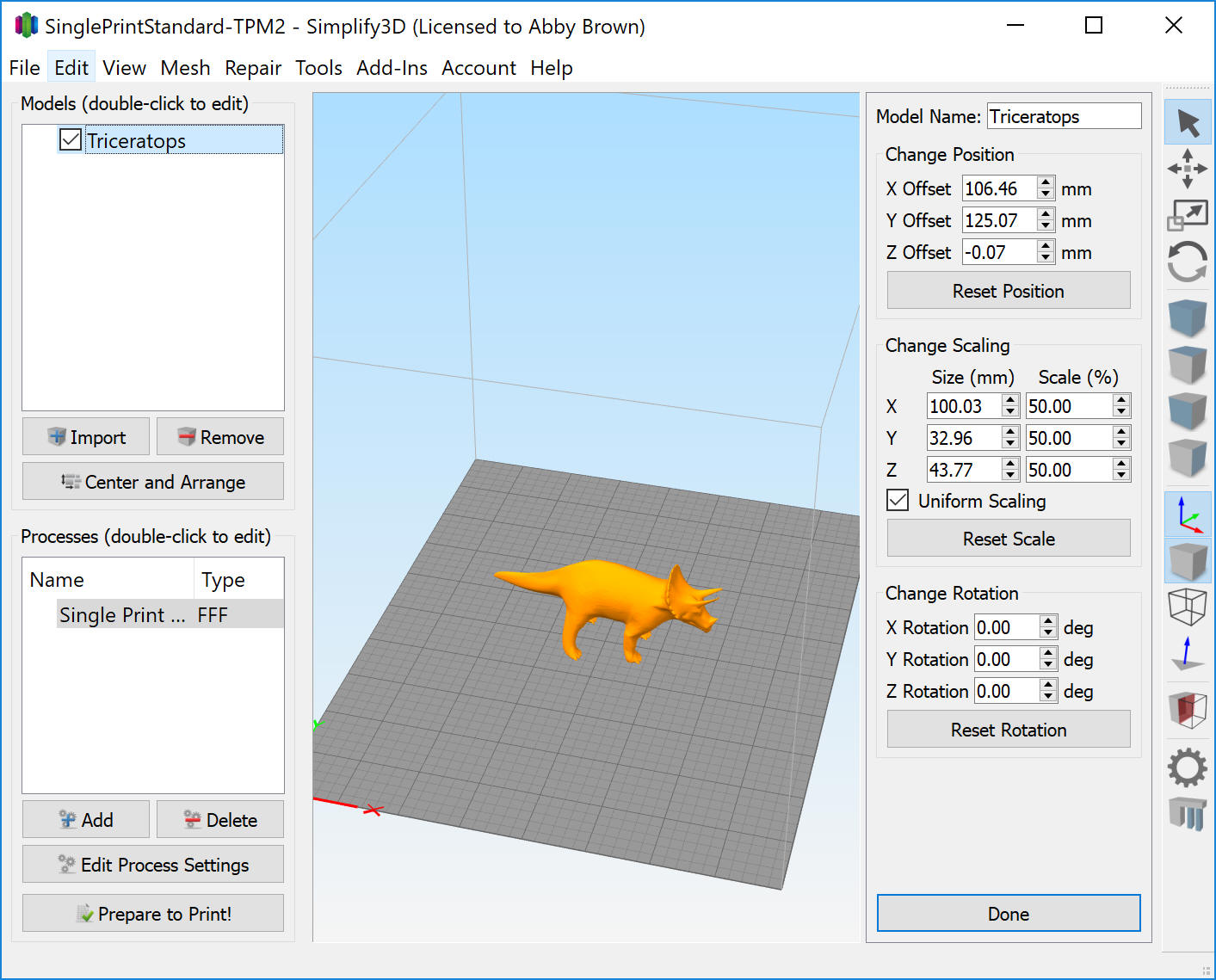 There
are a couple different ways to interact with the model for arrangement. I prefer
to double-click the model directly (or the name of the model in the box on the
upper left) to open a toolbar of options on the right. Under "Change Scaling"
change one of the 100.00% values to 50%. All of the x, y, and
z measurements should remain in proportion as long as the "Uniform Scaling"
box is checked. Note that all measurements are in millimeters (mm).
There
are a couple different ways to interact with the model for arrangement. I prefer
to double-click the model directly (or the name of the model in the box on the
upper left) to open a toolbar of options on the right. Under "Change Scaling"
change one of the 100.00% values to 50%. All of the x, y, and
z measurements should remain in proportion as long as the "Uniform Scaling"
box is checked. Note that all measurements are in millimeters (mm). Click
on the "Prepare to Print!" button in the lower left corner to access the print
preview. Take a look at the different elements. If everything is one color, on
the right find the "Coloring" option and choose "Feature Type" from the dropdown
menu.
Click
on the "Prepare to Print!" button in the lower left corner to access the print
preview. Take a look at the different elements. If everything is one color, on
the right find the "Coloring" option and choose "Feature Type" from the dropdown
menu. Click
"Exit Preview Mode" in the lower left to return to the main screen. We are now
going to adjust one of the details within the process settings.
Click
"Exit Preview Mode" in the lower left to return to the main screen. We are now
going to adjust one of the details within the process settings. Return
to the print preview mode. Move the "Max" slider to see the inside of the model.
Return
to the print preview mode. Move the "Max" slider to see the inside of the model. This
model would benefit from a raft. The feet and supports could have trouble
sticking to the bed. Also, a raft helps level out any uneven surface on the
print bed, such as when it is covered in tape. Rafts can affect the bottom of
the completed model, but in this case that would just be the feet. Overall, the
raft will be helpful in this case.
This
model would benefit from a raft. The feet and supports could have trouble
sticking to the bed. Also, a raft helps level out any uneven surface on the
print bed, such as when it is covered in tape. Rafts can affect the bottom of
the completed model, but in this case that would just be the feet. Overall, the
raft will be helpful in this case. Once
you have all of the settings as desired, you are ready to create the g-code.
First, if you have not done so already, I recommend that you save your .factory
file and give it a new name. Use "Save Factory File As..." within the File menu.
Once
you have all of the settings as desired, you are ready to create the g-code.
First, if you have not done so already, I recommend that you save your .factory
file and give it a new name. Use "Save Factory File As..." within the File menu.